Introduction
pntOS (position, navigation, and timing Operating System) is a government-owned fully-modular architecture for building navigation systems. It is designed so that a system can be created from a mixture of proprietary and government-owned components.
Motivation
Most PNT systems are “stovepipe” systems that are designed for a specific configuration of sensors to solve a particular PNT need. PNT threats are evolving rapidly. In particular, GPS-denied environments are becoming more common. Complementary PNT approaches mitigate these threats but changing current PNT systems is a slow and expensive process.
pntOS is designed to address this situation. It has broken up the concept of a PNT system into its component pieces (called plugins) and defined an Application Programming Interface (API) to standardize their interactions, allowing for plugins to be individually swappable. In order to foster community use and development, pntOS is fully government-owned. While some plugins may be open-source, plugins could be closed-source, allowing for proprietary algorithms to be used in pntOS.
While pntOS is analogous to an operating system in its functionality, it is not a true operating system. For more information, see Is pntOS an operating system?.
pntOS High Level Overview
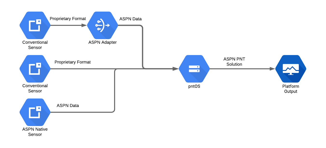
First let’s look at pntOS as a black box. It accepts measurements from various sensors, performs data fusion or filtering, and produces a navigation solution. All navigation data used internally in pntOS is ASPN-formatted data. Most sensors do not output ASPN data so the data needs to be converted before it can be used. This can happen in a few places:
In between the sensor and pntOS
In the pntOS
Transport pluginIn the sensor itself
The following image illustrates these operating modes in order from top to bottom respectively:
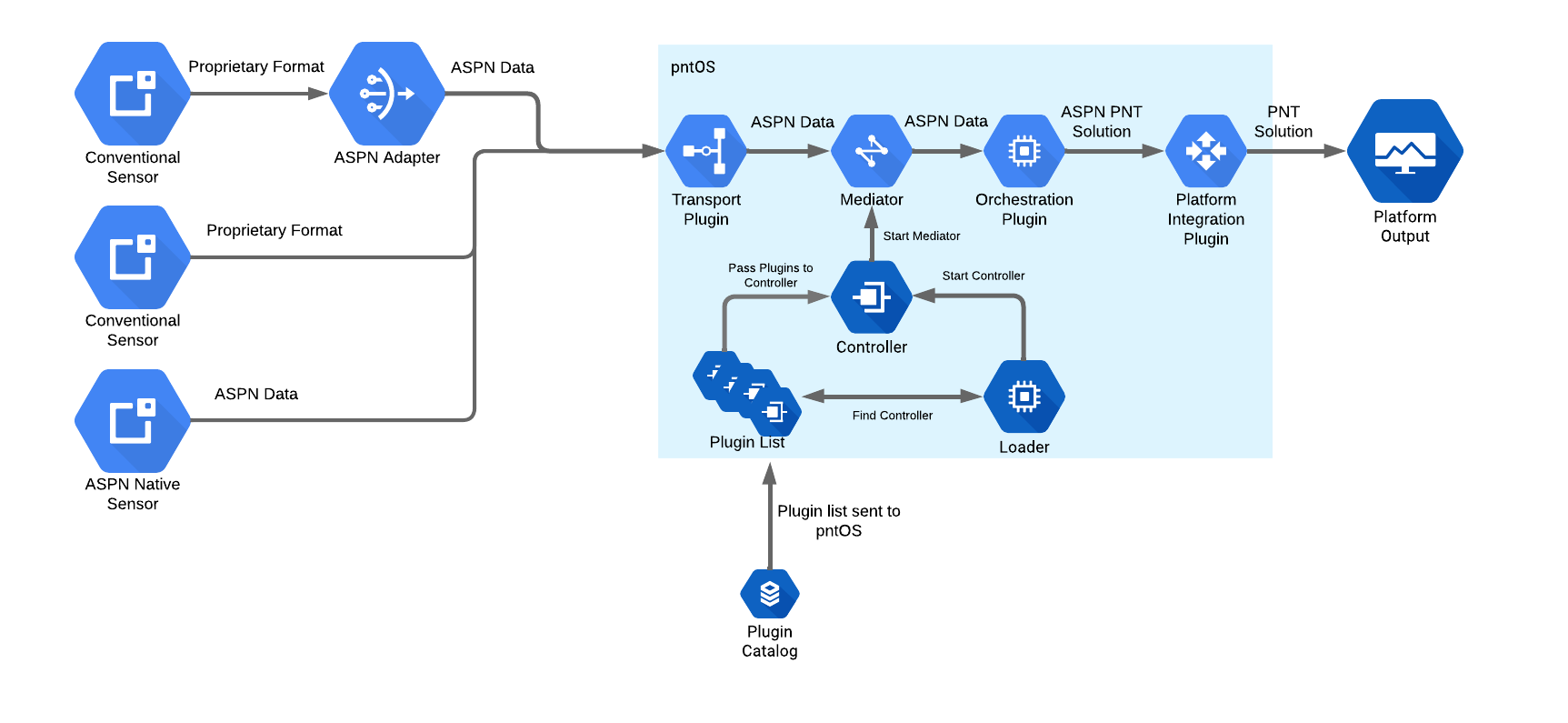
Next we’ll open up the pntOS box and discuss some of the core components and plugins that make up pntOS.
pntOS Components
We will start at the bottom of the diagram with the Loader and work our way
through the control flow.
Loader (Hosted Environment)
Although pntOS can run on bare metal, in this section we will assume we are running in a hosted environment, like running as an application on Linux or a real-time operating system (RTOS).
The pntOS daemon starts by the user calling the Loader with a list of
plugins. This is typically done by the user running a binary executable which in
turn invokes the main function in the loader. A list of paths to the locations
of dynamically-linked libraries containing plugins is passed to the executable
as command line parameters. The Loader then opens the dynamic library file
corresponding to each plugin and component it was passed. It scans the list of
plugins for one (and only one) Controller Plugin. Then the Loader hands
over control (by calling take_control) of the
process to the Controller Plugin. When this occurs, the loader passes
the list of all the other plugins it found in the shared libraries earlier to
the controller as a parameter.
Controller
From this point forward, the Controller Plugin is responsible for all activity
in the daemon. It may use any of the plugins it was passed as desired. The Controller Plugin defines any and all I/O (Input/Output) it supports, which pntOS plugins
are loaded or used, and the type of fusion being done. The Controller Plugin
should be written generically to support arbitrary run-time environment sensing.
Outside of some initialization in the Loader, the Controller Plugin is the
conceptual “main” function of the pntOS daemon.
The controller’s main responsibility is to choose and initialize the concurrency model being used by pntOS. For example, a controller might decide on a multithreaded implementation, or a multiprocessed implementation for better isolation and security. A simple controller might create a single thread for each plugin it was given and then set up thread-safe communication pipes between those plugins.
Mediator
Named after the computer science “mediator design pattern” concept, the
Mediator is an object created by the Controller Plugin and handed to each
plugin. It encapsulates communication and shared state between the plugins.
Before the controller may use any of the plugins it was passed, it must first
call the init_plugin function on that plugin and
pass into it a Mediator. The Mediator object is the only way that plugins
may communicate back to the Controller Plugin, by invoking the function
pointers on the object.
The Mediator therefore is where concurrency and synchronization are decided.
Continuing the example of a multithreaded implementation where each plugin is in
a separate thread, the Controller Plugin might implement a simple Mediator
by creating and storing internally a set of mutex locks, one per thread, and
then locking each call to a Mediator function using a mutex. The Mediator
function calls would then consist of locking logic followed by routing calls
from one plugin to another. In our current example illustrated in the above
diagram, we are routing data the Transport plugin received from a sensor through
the Mediator, which in turn (after synchronization according to its
concurrency model) sends the data on to the Orchestration plugin.
As another example, suppose instead we were writing a multiprocessed controller.
In this case, the controller might fork() to put plugins into their own
processes, and then write a Mediator that opens IPC communication primitives
(such as /dev/shm or sockets) in order to route the data from the Transport plugin to the Orchestration plugin, which are now in different processes. Thus the
Mediator that is constructed by the Controller Plugin is tied closely to the
concurrency model chosen by the Controller Plugin.
Transport
The Transport plugin receives messages from various sensors, sends responses
back to sensors as needed, and broadcasts the pntOS solution from the
Orchestration plugin. Its primary responsibility is receiving sensor data from
the network, converting it to ASPN format, and then forwarding it onward to the
mediator.
Orchestration
The pntOS Orchestration plugin contains the core navigation data fusion and
filtering functionality. It is responsible for calculating a navigation
solution from the incoming sensor data. It performs this task by calling out to
various plugins which define the actual sensor fusion algorithm, state space,
and sensor error models. Thus its primary duties are to orchestrate the flow of
data into/out of filters, and picking the set of navigation-related plugins which
are used to model errors and generate estimates.
Platform Integration
The Platform Integration plugin is an optional plugin. It converts the outgoing
navigation solution from an ASPN format to any other format required by the
user. We’ll look at how this plugin interacts with the rest of the system in
more detail in Platform Integration Plugin Interactions.
Orchestration Plugin Components
Next, let’s dive into the components and plugins that make up the
Orchestration plugin.
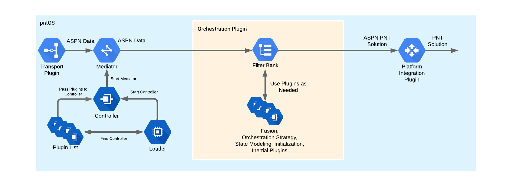
The Orchestration plugin could be a single black box solution or broken up
into more modular components. In the latter case, a bank of one or more filters
has access to a bank of filtering plugins. Filtering plugins might include the:
Orchestration Strategyplugin
Orchestration Strategy
The Orchestration Strategy plugin is relatively tightly involved with the
Orchestration plugin. It is responsible for ensuring that the pntOS solution
is robust and resilient to sensor faults. This could range from protecting
against faulty sensors, to improper state models, to malicious attacks from an
outside party.
Fusion
The Fusion plugin accepts sensor measurements (and possibly a reference
Position-Velocity-Attitude (PVA) solution from the Inertial plugin) via the
Orchestration plugin and passes them to the Fusion Strategy plugin. It does
all the book-keeping to keep track of which state blocks and measurement
processors correspond to which states in the Fusion Strategy plugin.
Fusion Strategy
The Fusion Strategy plugin does the core estimation work. It determines what
type of estimator is used, such as an Extended Kalman Filter (EKF),
Rao-Blackwellized Particle Filter (RBPF), or something else. It receives models
from the state blocks and measurement processors in the State Modeling plugins via
the Fusion plugin and propagates and updates its states accordingly.
Inertial
The Inertial plugin receives an initial PVA alignment and IMU (Inertial
Measurement Unit) measurements which it mechanizes to produce an INS (Inertial
Navigation System) solution. This plugin may also handle resets and feedback
from the Orchestration plugin.
Initialization
This plugin uses sensor data and user inputs received from the Orchestration plugin to calculate
an initial solution. This could be a PVA used as the starting point for the INS solution generated
by the Inertial plugin or an estimate and covariance used to initialize a state block.
State Modeling Plugin Components
Last, let’s take a deeper look into the State Modeling plugin.
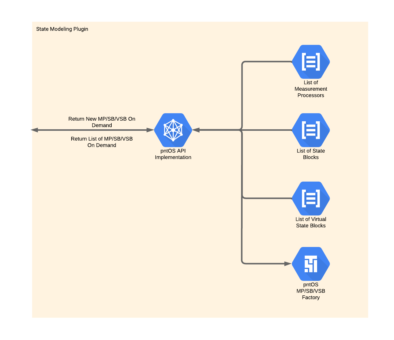
This plugin contains lists of Measurement Processors, State Blocks, and
Virtual State Blocks and a factory to construct them. At the Fusion plugin’s request it constructs these objects and returns them to the Fusion plugin.
Below is some very brief information about Measurement Processors, State Blocks, and Virtual State Blocks, as well as links to sections with
more information.
Measurement Processor
Measurement Processors are responsible for providing the model that the
Filter Strategy uses to update its states given a sensor measurement. For more
detailed information on the function of Measurement Processors, see
Measurement Processors.
State Block
State Blocks provide the Filter Strategy with states and a model to
propagate those states. For more detailed information on the function of State Blocks, see State Blocks.
Virtual State Block
Consider the case where a given State Block provides three
Latitude-Longitude-Altitude (LLH) states and a given Measurement Processor
provides a model to update three Earth Centered, Earth Fixed (ECEF) position
states. Normally this Measurement Processor and State Block would be
incompatible with each other, but a Virtual State Block that converts between
ECEF position and LLH position could bridge the gap.
In short, Virtual State Blocks convert the states provided by State Blocks. For more detailed information on the function of State Blocks,
see Virtual State Blocks.
Platform Integration Plugin Interactions
Let’s move back to the Platform Integration plugin to examine it in more
detail. One of the tasks of this plugin is to handle all of the
platform-specific messages that might be needed and it is impossible to
enumerate all the possibilities here. Instead, we’ll try to focus on some of
the most common interactions here.
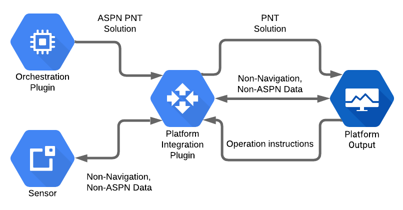
The graphic above shows some of the typical interactions between the Platform Integration plugin and other pieces of the system.
As alluded to in the Platform Integration section, when a platform needs
the navigation solution in a non-ASPN format, it is the Platform Integration plugin’s job to convert the ASPN navigation solution from the Orchestration plugin into the desired format and send it to the platform output.
The system may need the sensors to change operation. In this case, the
Platform Integration plugin may send mode messages to the sensors with
instructions to change the output frequency, consume a different amount of
power, etc. Conversely, the sensors may have non-navigation data to send to the
system. The Platform Integration plugin will convert and forward any such data
from the sensors to relevant parts of the system.
Similarly, the platform and pntOS may need to exchange non-ASPN data or
instructions. For example, the platform may instruct pntOS to start filtering,
enter a standby state, change the output rate, etc. The Platform Integration plugin will handle all these interactions as well, acting as the liaison
between the platform and pntOS.
Another View of pntOS
At this point, now that we’ve gotten some understanding of the core components and plugins in pntOS, let’s take a look at everything all together and define some of the smaller plugins.
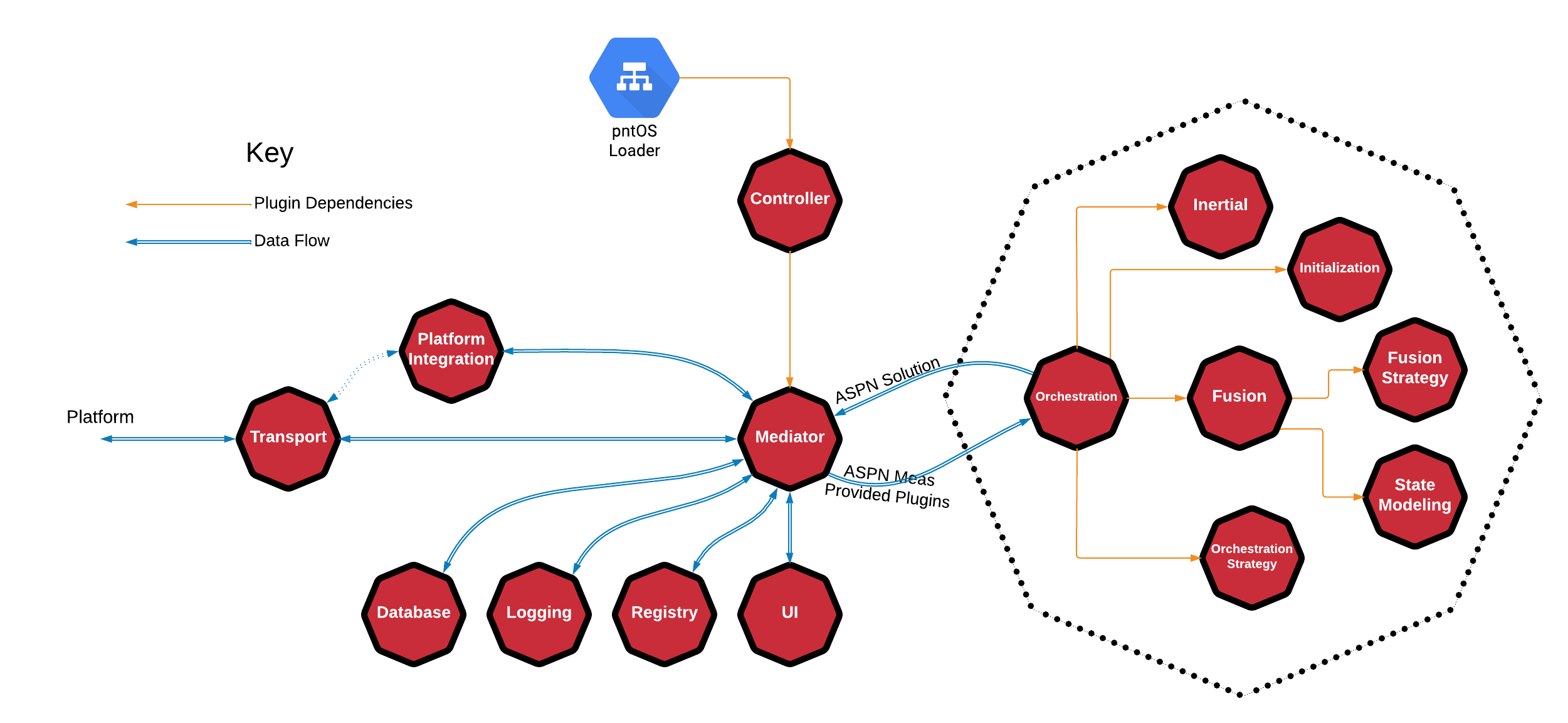
This graphic shows how the Orchestration plugin relates to pntOS as a whole,
but also the relationship of the plugins that make up the Orchestration plugin by encapsulating them all within a dotted octagon.
The figure also shows an optional relationship between the Transport plugin
and the Platform Integration plugin by using a dotted arrow line. This
indicates that the Platform Integration plugin is allowed to use the Transport plugin for input and output.
So far we’ve discussed the Loader, Controller Plugin, Mediator,
Transport plugin, Platform Integration plugin, Orchestration plugin,
Fusion plugin, Fusion Strategy plugin, State Modeling plugin, Inertial plugin,
Initialization plugin, and Orchestration Strategy plugin. Next we’ll move on to the
remaining plugins: the Database plugin, Logging plugin, Registry plugin,
and User Interface plugin.
Database
Database plugins provide the system with navigation data. For example, some
systems might require DTED (Digital Terrain Elevation Data).
Logging
The Logging plugin records messages to an arbitrary sink (e.g. console, file,
network, etc.).
Registry
The Registry plugin implements a global key-value registry. See
pntOS Registry Overview for more information on the Registry plugin.
UI
The User Interface plugin implements a UI that is integrated directly into
pntOS. While it is always possible to write a Graphical User Interface (GUI)
that listens to pntOS outputs and interacts with it externally, this plugin
allows users to write a GUI that has direct access to pntOS via the plugin API.
This allows for low latency and high performance GUI/UIs to be generated. Note
that this plugin is designed for developer or research style UIs and not
production environments. A user display in a production environment is better
modeled as a Platform Integration plugin, as that is designed to represent
requests from the system and not simply status updates.